Virtual Reality and Stereography in Biomedical Visualization
Luc Renambot
2012 Spring
Electronic Visualization Laboratory
University of Illinois at Chicago
Interactive Presentation of a Clinical Case Report with Unity3D
Objective: Generate a medical application such as a presentation, game or app utilizing Unity3D while incorporating the concepts of 3D perception, 3D model creation and virtual reality in medicine.
What is Unity3D?
Unity3D is an integrated development engine for the creation of interactive 3D content for multiple platforms including Mac OSX App, Windows Executable, Web Browsers (using the Unity WebPlayer), iPhone, iPad, Android phones and tabliets, Wii, PS3 and Xbox 360.
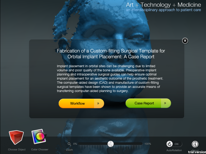
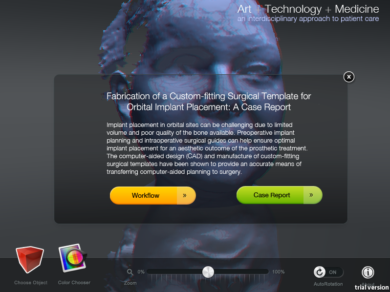
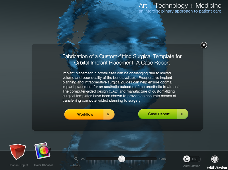
Overview: The splash window of the presentation provides a brief introduction of the case report and links to an in-depth workflow of the surgical template fabrication and the clinical case report. The interactive presentation showcases medical models of the patient��s facial surface topology, skull, skull with surgical template and implants planned in place, and a final model of the patient��s face with implants. Additional stereoscopic versions were generated in anaglyph, interlace and user customizable modes.
Process:
3D Model Creation
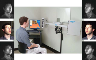
The patient��s facial topology was captured with the 3dMDface system in the Craniofacial Center at the University of Illinois Medical Center. The 3dMD system utilizes Digital Surface Photogrammetry (DSP) to capture the 3D form by projecting a random light pattern with synchronized digital cameras set at various angles. By filtering different wavelengths of light, a 3D surface geometry and surface texture are acquired simultaneously, resulting in an accurate texture map when applied to the surface data. The model was exported as a standard tessellation language (STL) format.
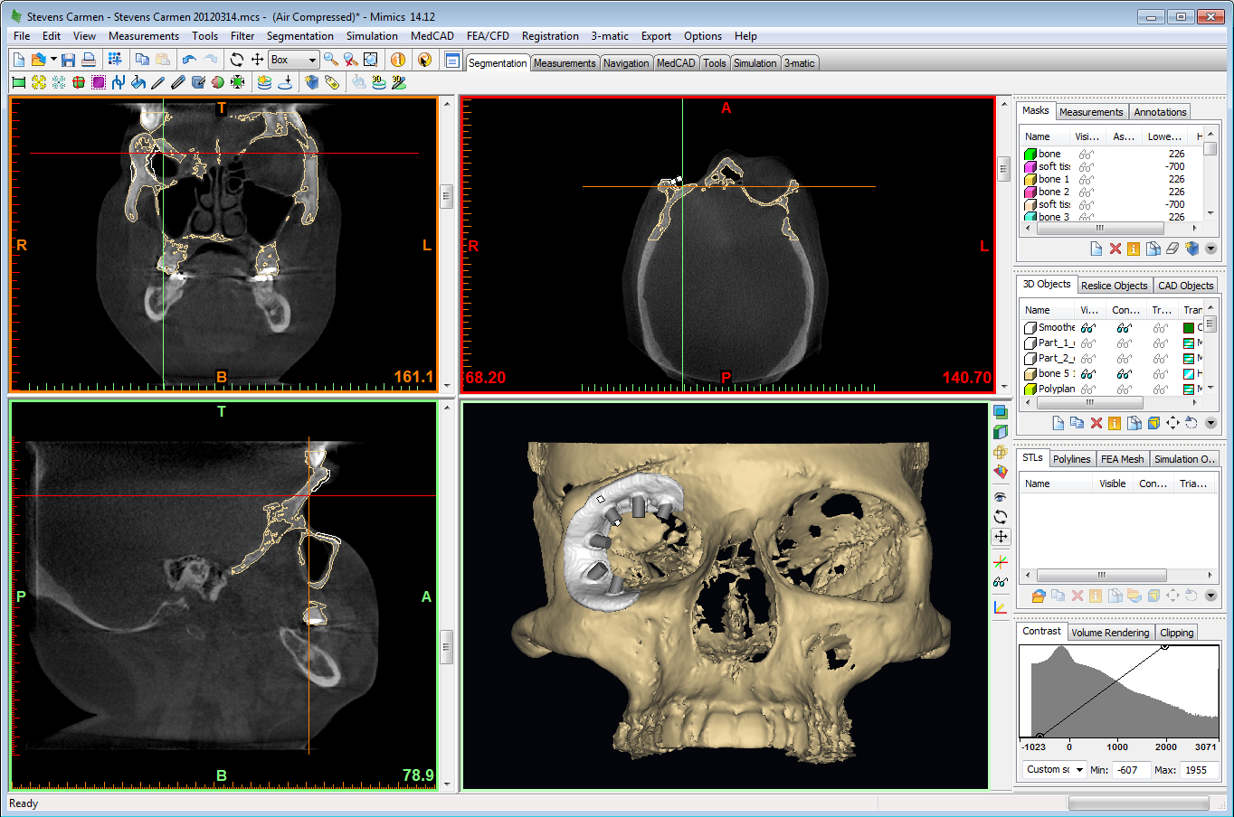
 The cone-beam computerized tomography (CBCT) scan that had already been acquired for the diagnosis and surgical planning of the patient was exported in DICOM (Digital Imaging and Communications in Medicine) format and imported into Mimics (Materilise NV), a medical data transfer software. Mimics was used to segment out the patient��s skeletal anatomy, plan implant placement, and fabricate a surgical guide for the designated implant. The 3D models of the partial skull, surgical template and implants were exported as .STL files.
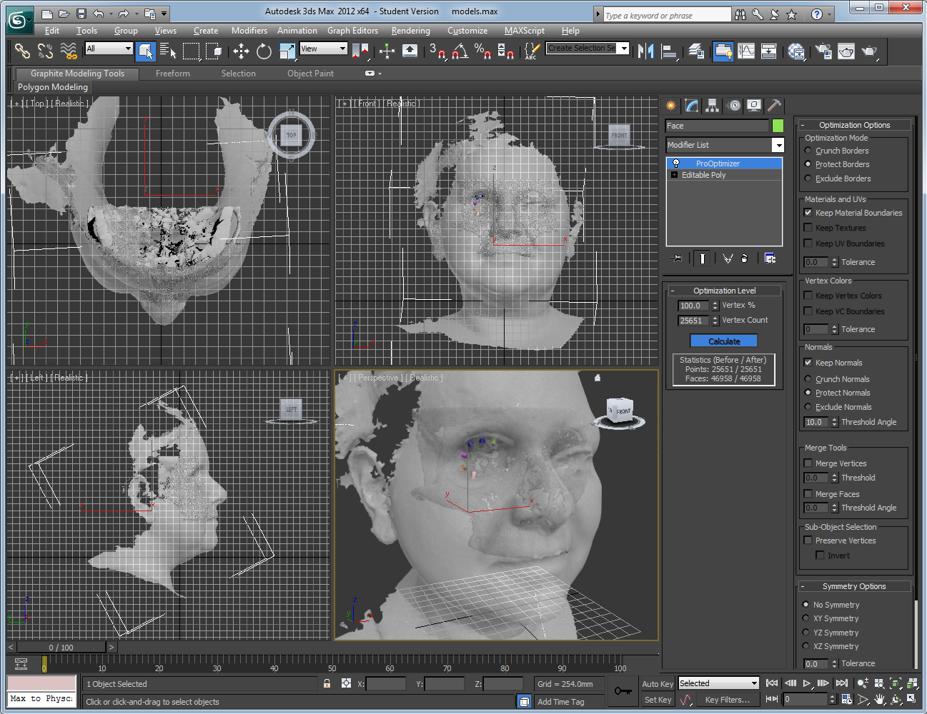
 With the emphasis on real-time 3D interaction, Unity3D has a 65,000 vertix loading limit. This was problematic for the models generated from medical CT with extremely dense meshes. Also, since Unity3D does not support .STL files, the 3D model files needed to be converted into one of the following formats supported by Unity: .FBX, .dae, .3DS, .dxf and .obj files. Thus, I imported all the 3D models into Autodesk 3ds Max, converted them into edible polys and placed a ProOptimizer modifier on each model to reduce the vertices to under 65,000. Each model was then correctly oriented and placed in relations to one another and exported as .FBX files.
Unity3D
Unity3D was downloaded and installed. The Unity Pro trial was activated to enable a richer, more powerful feature set including more options for post-processing special effects, pathfinding, light effects, and performance optimization. An asset named SampleStudio with SlidingMenu was downloaded and imported into the 'Assets' folder.
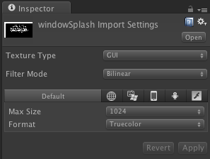
 A splash window was created with a graphical user interface (GUI) texture with a 'Window' script attached. The GUI texture was made in Adobe Photoshop with the project title and description on a semi-transparent background saved as a portable network graphics (PNG) file. The .png file was imported with the ��Texture Type�� set to ��GUI�� and ��Format�� set to ��Truecolor�� in the inspector panel.
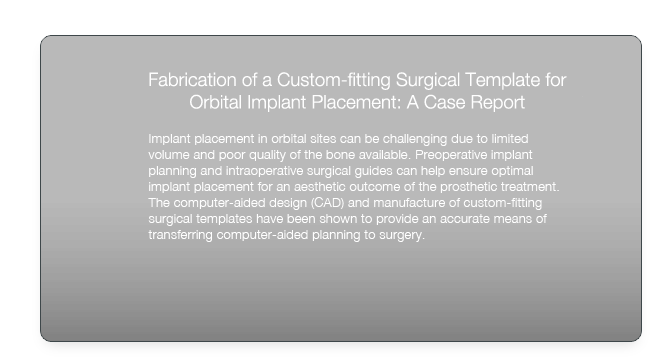
 The attached ��Window�� script calls the splash window upon start and adds two buttons that link to the in-depth workflow and case report for more information.
 The buttons were created in Adobe Photoshop with a hover state and were all saved as .png file format. The splash window can be closed and recalled with the ��About�� button on the GUI menu.


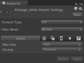
A logo with a tagline visible on the upper right was created with a GUI texture. The GUI texture was again made in Adobe Photoshop with the logo and the tagline on a transparent background and saved as a .png file. The file was imported with the ��Texture Type�� set to ��GUI�� and ��Format�� set to ��Truecolor��.

 The models of the face, skull, guide and implants were imported and placed into the scene under 'Models' to replace the original placeholder models. 'Model_1' as the patient��s face, 'Model_2' as the patient��s partial skull, 'Model_3' as the surgical guide, 'Model_4' as the skull with the guide and implants, and 'Model_5' as the patient��s face with the implants in place. Once all the models were correctly oriented and placed, they were dragged into the '_prefabs' folder to generate the prefabs of the same models.
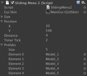
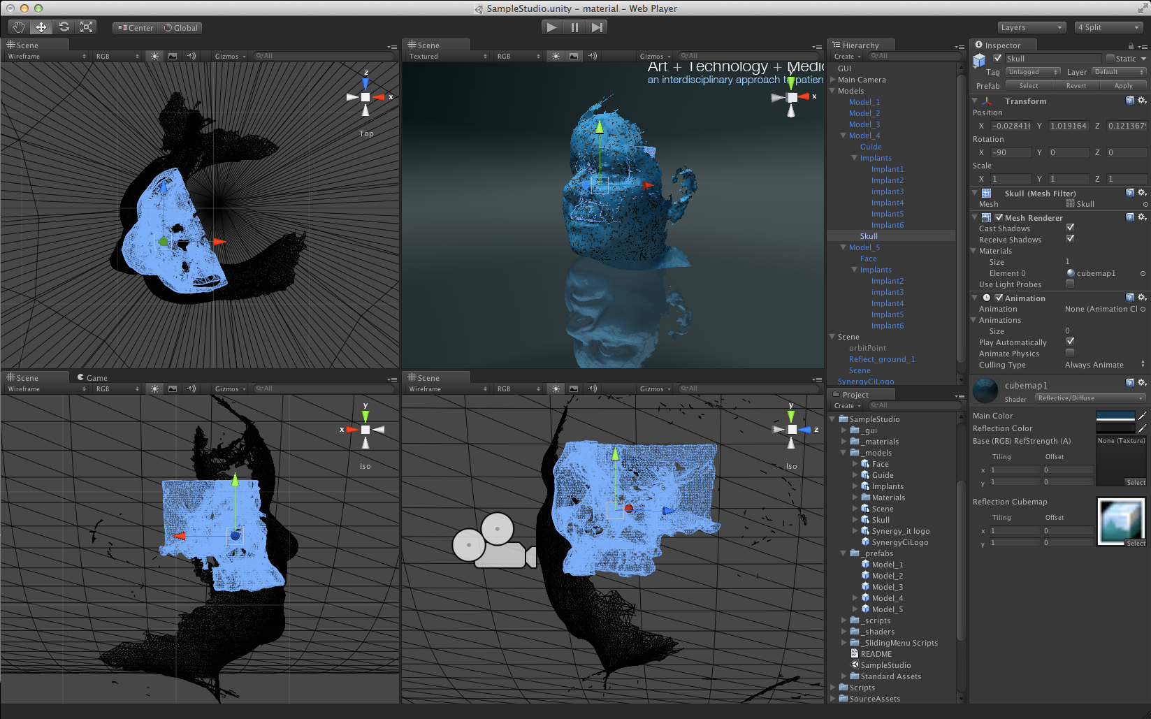 The prefabs are then linked to the ��SlidingMenu2�� script attached to GUI for the models to be called when the appropriate button is clicked on the 'Choose Object' sliding menu.
 The buttons of the models on the 'Choose Object' sliding menu were created in Photoshop each with a hover state on a transparent background. They were exported as .png files and replaced the original button icons respectively as 'Model_1', 'Model_1h', 'Model_2', 'Model_2h', 'Model_3', 'Model_3h', 'Model_4', 'Model_4h', 'Model_5', and 'Model_5h'.


To slow down the autorotation of the camera around the models, the 'MouseOrbitMenu' script attached to the camera was modified. The 'autoRotate' code under 'StartRotate' was modified from 0.8 to 0.3 frames.
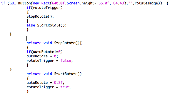 The 'MouseOrbitMenu' further enables interactivity with the user��s mouse. The attached 'Zoom' script enables camera zoom with the GUI zoom slider button and the mouse scroll.
Stereo 3D
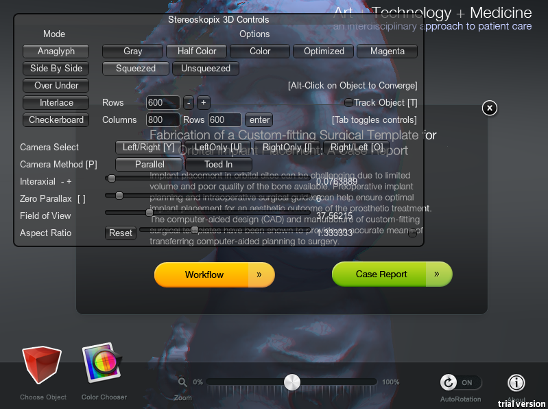
The 'stereoskopix3Dv027demo.unitypackag'e was downloaded and placed in Applications > Unity > Standard Package. The package was then imported into the existing Unity project. The 'steroskopix3D' script was dragged onto the main camera. The ��stereo3DMat�� material was placed into the ��Stereo Materials�� field. In the game mode, the parameters were adjusted with the GUI controls for proper stereo 3D perception. The adjusted settings were recorded.
 After exiting the game mode, the new settings were entered in the camera inspector. ��GUI Visible�� was unchecked to hide the GUI controls in the game mode.
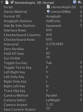 The project was then rendered in the 3D formats of anaglyph, interlace, and anaglyph with visible GUI controls for the user to manipulate.
Final Words
It��s been an incredible learning experience with so much more to discover! Many thanks to my classmates Semay and Ada for all their support and assistance! And of course, boundless gratitude to Luc Renambot for going above and beyond to help each one of us with our endless questions and problems. Also, I apologize for having started the never-ending story of the 3D camera adapter.
Just for fun, click on the egg!
